What is this about?
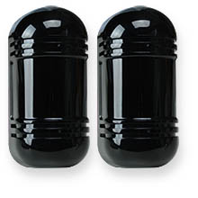
Perimeter intruder detectors for burglar alarm and CCTV systems.
Product codes
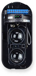
AN-B1
100 m. infrared barrier for outdoor.
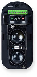
AN-B1C
100 m. infrared barrier for outdoor.
With coding + anti-fog
Further
information
Technical
datasheet
|
|
PRODUCT RANGE

 AN-B1
AN-B1
INFRARED BEAM DETECTOR
100 m. range - Dual beam


 AN-B1C
INFRARED BEAM DETECTOR
100 m. range - Dual beam
With anti-fog system
Frequency coded for overlap mounting


PRODUCT INCLUDES

 Transmitter
 Receiver
 Pole mounting brackets
 Drilling mask

TECHNICAL DATA

 datasheet datasheet

|
|
General description
These infrared barriers are composed of a transmitter element and a receiver
between which an invisible double infrared beam is transmitted. If the
infrared beam is interrupted by the passage of an intruder, the receiving
unit switches an alarm contact which can activate an alarm system or the
alarm functions of a CCTV video recorder.
Waterproof transmitter and receiver
A complete detector consists of a transmitting unit, which generates the infrared beam, and of a receiver, which provides the alarm contact. The two elements of the barrier are enclosed in an elegant container in
black glossy polycarbonate that can be mounted both indoors and outdoors.
These barriers are mounted directly on the wall with the two screws included, or on poles. 2 metal clamps for pole mounting are supplied with the product.
100 m outdoor / 300 m. indoor detection range
The maximum distance between transmitter and receiver is 100 meters outdoor. When used indoors, the
detection range increases up to a maximum of 300 meters. For good operation
at maximum distance it is essential that the barriers are installed on absolutely stable supports and are correctly aligned.
Dual beam for false alarm immunity
The infrared beam of these barriers is actually composed of 2 overlapping
beams. To generate an alarm, both beams must be interrupted in a defined
time. The double beam feature is essential to avoid unwanted triggering due to the leaves, birds or insects.
Adjustable response time
With a trimmer in the receiver it is possible to adjust the sensitivity of the barrier.
Adjusted to maximum sensitivity, the barrier detects the passage of any intruder, even very fast, which interrupts the infrared
beam for a very short time.
If the barrier is placed around a fence, where a fast crossing is presumably
impossible, you can set a longer response time to increase immunity to false detections.
Frequency coding for barrier overlap
The AN-B1C model allows you to set a coded frequency for each barrier so that the transmitter only dialogs with its paired receiver. This function is important if several barriers are installed near or overlapping each other, in order to avoid that a receiver is influenced by the IR beam of other transmitters.
AN-B1C allows to set up to 8 coded frequencies, selectable by the user.
Below we show an example of a few overlapping barriers that create a virtual fence.

Anti-Fog feature
The infrared barriers can not operate in case of strong fog as this brake
the line of sight between the transmitter and the receiver which is
essential for their operation. The AN-B1C model is equipped with an anti-fog
protection system that is able to exclude the barrier in case of strong fog
and to re-activate it when normal visibility is restored.
The receiver of this model come with a relay output that activates when the
anti-fog protection is on.
Wiring
Both the transmitter and the receiver module must be powered with a voltage
between 12VDC and 24VDC. The low power consumption of these devices (max
65mA) makes it possible to support long power cabling: up to 300 m. with 0.5 mmq
cables and up to 1000 m. with 2 mmq cables.
Both modules have a TAMPER
contact output.
The receiver module provides a NO / NC alarm contact that switches for 2 seconds in the event of an alarm.
This alarm contact must be connected to the alarm input of the device that will perform the alarm actions,
like of an alarm system or a DVR.
Alignment
It is necessary that these barriers are well aligned to
work properly. For this reason both the transmitter unit and the receiver
unit have adjustment screws that allow the infrared beams to be oriented (+/- 90 ° horizontal and +/- 10 ° vertical).
All models have a system for indicating the IR signal level, placed in the receiver, which allows you to adjust
the alignment easily. The AN-B1C model shows the power of the IR signal on the embedded display,
while the AN-B1 model, which has no display, provides a voltage output to be
measured with a tester.
 |

|
AN-B1 |
AN-B1C |
|


